Confused about sheet metal tolerances? This plain-language guide explains what to expect from cutting, folding, and forming accuracy, and why ISO 9001 certified fabricators like Ashland Engineering consistently deliver parts that meet the mark.
When you order sheet metal parts, you expect them to fit. You expect holes to align, bends to land at the right angle, and finished components to drop straight into their assemblies without rework.
However, sheet metal tolerances are frequently misunderstood. Many buyers apply machining expectations to a fundamentally different process. The result is drawings that are either over-toleranced, driving up cost unnecessarily, or under-toleranced, causing assembly problems that were entirely preventable.
This guide explains sheet metal tolerances in plain language. By the end, you will know exactly what to expect from each process stage, how to specify tolerances that work, and why an ISO 9001 certified fabricator makes all the difference.
What Are Sheet Metal Tolerances?
A tolerance defines how much a finished dimension can vary from the value stated on the drawing. Every fabrication process introduces some degree of variation. Tolerances set the acceptable limits within which that variation must stay.
Sheet metal tolerances cover several types of measurement. Linear tolerances govern lengths, widths, and hole positions. Angular tolerances govern bend angles. Geometric tolerances govern flatness, straightness, and the positional relationship between features.
The key point to understand is that sheet metal fabrication is not machining. Machining removes material from a rigid block in a single controlled setup. Sheet metal fabrication reshapes material across multiple process stages, each of which introduces its own variation. Consequently, the tolerances achievable in sheet metal are fundamentally different from those in CNC machining.
The Industry Standard: ISO 2768
The most widely used tolerance standard in UK sheet metal fabrication is ISO 2768. It defines general tolerances for linear and angular dimensions without needing every feature called out individually on the drawing.
ISO 2768 medium grade, denoted ISO 2768-m, is the standard for commercial and industrial sheet metal work. It specifies ±0.15mm for dimensions up to 30mm, ±0.2mm for 30 to 120mm, ±0.5mm for 120 to 400mm, and ±0.5 degrees angular. Adding the note “GENERAL TOLERANCES: ISO 2768-m” to your drawing title block means all dimensions not individually called out conform to this standard.
For most commercial and industrial applications, ISO 2768-m is entirely sufficient. Specifying ISO 2768 fine grade when medium would suffice adds approximately 20 to 25 percent to the total fabrication price, through tighter CNC programming, slower cutting speeds, and increased inspection scope.
Understanding this helps buyers make smarter specification decisions from the outset.
Tolerances by Process Stage
Sheet metal parts travel through multiple process stages before completion. Each stage has its own achievable tolerance range, and understanding each one helps you specify parts that are both accurate and cost-effective.
Laser Cutting Tolerances
Laser cutting is the most precise stage in the sheet metal fabrication process. Fibre laser cutting achieves positional accuracy of approximately ±0.05mm, which corresponds to ISO 2768 fine grade. This represents the tightest sheet metal tolerance achievable at the cutting stage.
However, heat affects the material during laser cutting. As the laser travels across the sheet, it introduces heat into the metal, causing expansion. By the time cutting is complete, thermal effects may have displaced features on larger parts. When the sheet cools, internal stresses can cause the panel to warp rather than return to perfect flatness.
Therefore, for large flat parts with precise hole patterns, discuss thermal effects and nesting strategy with your fabricator before finalising your design.
CNC Press Brake Bending Tolerances
Bending introduces more variation than cutting. CNC press brake bending typically achieves angular tolerances of ±0.5 degrees and linear tolerances of ±0.4mm to ±0.8mm for post-bend dimensions.
The reason for this wider tolerance range is springback. Every bend involves springback, the material’s partial return toward flat after forming. Springback varies with material type, grain direction, thickness, and tooling condition. Consequently, formed dimensions should not carry the same tolerance expectations as cut features.
Furthermore, when holes are on different surfaces separated by multiple bends, tolerances stack up across each bend. The positional tolerance of a hole on a flat plate and the same hole measured across four bends from a reference on another face are entirely different figures.
The practical takeaway is straightforward. Dimension critical features from the same flat surface wherever possible. Avoid expecting cut-feature tolerances to hold across bend lines.
Welding Tolerances
Welding introduces the widest variation of any sheet metal fabrication stage. Welding tolerances typically range from ±0.5mm to ±2mm for linear dimensions, and angular dimensions are usually within ±2 degrees. EVS Metal
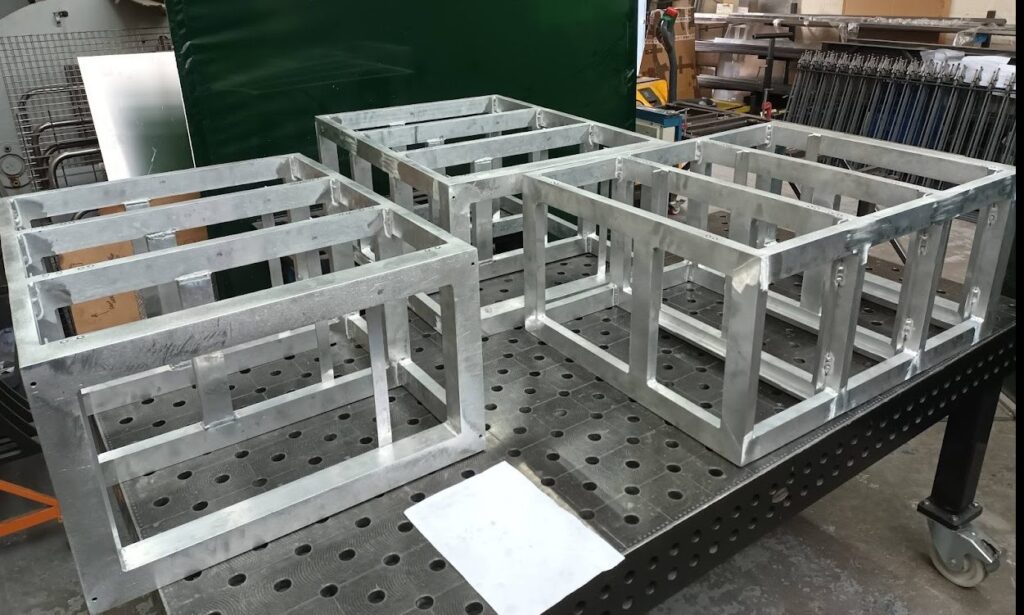
Heat input during welding causes distortion. Using fixtures for welding and adding clamps or chill bars reduce distortion. Sizing jigs after welding can bring parts back within tolerance limits when needed.
A skilled fabricator controls weld distortion through planned weld sequences, proper jigging, and careful heat management. At Ashland Engineering, the welding team applies these techniques as standard, particularly on precision sheet metal assemblies where post-weld dimensions are critical.
What Affects Sheet Metal Tolerances
Several variables determine what tolerances a fabricator can reliably achieve on your parts. Understanding them helps you design parts that hit their tolerances consistently rather than occasionally.
Material Type and Thickness
Aluminium allows for moderate tolerances due to its ease of forming. Stainless steel requires tight tolerance control because of its lower ductility and springback behaviour. Carbon steel is formable and strong and permits moderate tolerances.
Material thickness adds further complexity. Thinner materials allow tighter tolerances, while thicker materials require looser ones. Each material type has particular properties that directly determine manufacturing accuracy and part performance.
Grain Direction
Sheet metal has a grain direction established during rolling. Bending a part parallel to the grain bends more easily but is more prone to cracking and offers less resistance to springback. Bending against the grain demands more force and alters the resulting bend radius.
Fabricators who understand grain direction plan bend orientations deliberately. This is part of the expert knowledge that separates a quality fabricator from one who simply loads a sheet and runs the programme.
Part Complexity and Tolerance Stack-Up
The more complicated the part, the harder it is to maintain tight tolerances throughout the geometry. Every bend, hole, and feature is another possible source of variation. These individual variations add up in what is called tolerance stack-up.
For complex multi-bend assemblies, work closely with your fabricator at the design stage. Ashland Engineering’s in-house CAD/CAM team reviews designs for tolerance achievability before production starts, flagging features that may cause stack-up problems and suggesting design adjustments that preserve function while improving manufacturability.
Machine Condition and Calibration
Even the best machines lose accuracy over time. Worn punches, dies, and cutting nozzles can produce inconsistent results. Regular calibration and tooling maintenance are essential to maintaining stated tolerances across production runs.
A skilled fabrication crew is familiar with the behaviour of various materials on their particular equipment. They maintain strong machine calibration, tool maintenance, and consistency processes. This is a practical reality that separates an experienced fabricator from a less well-maintained operation.
How to Specify Tolerances That Work
Over-tolerancing is one of the most common and costly mistakes buyers make on sheet metal drawings. A title-block tolerance of ±0.005 inches across an entire formed sheet metal part is likely to produce either a no-quote or a very expensive conversation. Achievable tolerances depend on material, thickness, part geometry, and equipment.
The practical approach is simple. Identify which dimensions are genuinely critical to fit or function. Apply tight tolerances only to those features. Apply ISO 2768-m to everything else using a single title block note.
Additionally, applying GD&T when controlling key elements such as datums, true position, and hole patterns ensures consistent assembly even when minor variations occur. For less sensitive dimensions, relying on ISO 2768 or shop-provided default tolerances keeps drawings clear and avoids unnecessary inspection work.
If you are unsure whether your tolerances are achievable or appropriate, ask your fabricator before finalising the drawing. A good fabricator reviews your design before quoting and highlights any features that will cause problems. This is exactly what Ashland Engineering does as standard.
Why ISO 9001 Makes Tolerances More Reliable
Achieving a stated tolerance once is relatively straightforward. Achieving it consistently, across every part in every batch, is where quality systems make the critical difference.
A strict quality control regime, certified to standards such as ISO 9001, ensures that parts are checked at key points throughout production and that processes are constantly reviewed and refined.
ISO 9001 certified companies maintain tolerances within ±0.005 inches for critical dimensions, with experienced manufacturers using advanced technology and skilled workers to reach tighter tolerances consistently. Proto Labs
Ashland Engineering holds full ISO 9001 certification to the latest standard. Their quality management system covers every stage of sheet metal production, from laser cutting and CNC press brake bending through to welding, finishing, and final inspection. Calibrated digital metrology tools verify critical dimensions at key stages, not just at the end of a batch.
This means you get consistent results on repeat orders. The tenth batch delivers the same dimensional accuracy as the first because the same controlled processes, the same calibrated equipment, and the same documented inspection procedures apply throughout.
Practical Tolerance Reference for Sheet Metal Buyers
Here is a quick reference to set realistic expectations when specifying sheet metal parts:
Laser cutting on flat sheet delivers positional accuracy around ±0.1mm on small features and ±0.5mm on larger parts. Fibre laser can achieve ±0.05mm on features under 100mm.
CNC press brake bending typically achieves ±0.5 degrees on bend angle and ±0.4 to 0.8mm on linear post-bend dimensions for standard gauges.
Hole positions on the same flat face are the most accurate dimensions on any sheet metal part. Keep critical holes on the same plane wherever possible.
Across-bend dimensions carry wider tolerances due to springback and tolerance stack-up. Avoid making these dimensions critical unless your fabricator has confirmed achievability.
Welded assemblies carry the widest tolerances, typically ±0.5 to 2mm on linear dimensions, depending on part complexity and fixturing.
Ready to Discuss Your Sheet Metal Tolerances With a Quality Fabricator?
Ashland Engineering delivers precision sheet metal fabrication backed by ISO 9001 certified quality, in-house CAD/CAM design review, CNC laser cutting, press brake bending, MIG and TIG welding, and calibrated dimensional inspection.
Based in Milton Keynes and serving customers across the UK, get in touch today at sales@ashlandengineering.co.uk or call 01908 382 599 to discuss your project and receive a competitive, detailed quote.