Wondering how the engineering design process works at a bespoke metal fabricator? This guide walks you through every stage, from initial concept to finished part, and explains what to expect when you work with Ashland Engineering.
Most people know roughly what a metal fabricator does. They cut metal, bend it, weld it, and finish it.
However, fewer people understand what happens before any of that starts. The engineering design process is where a project either sets itself up for success or creates problems that are expensive to fix later.
This post walks you through the full engineering design process at Ashland Engineering, from your first contact to the moment your finished part leaves the workshop.
Why Engineering Design Matters in Metal Fabrication
Engineering design is not just a preliminary step. It is the foundation every part is built on.
A poorly designed component can fail to fit, underperform in its application, or cost far more to manufacture than it should. Consequently, the time invested in good engineering design at the start pays dividends throughout the entire project.
At Ashland Engineering, engineering design is fully integrated into the manufacturing process. Their in-house CAD/CAM capability means design and production teams work together from day one. As a result, problems get identified early, not after material has been cut.
Stage 1: The Initial Enquiry and Concept Capture
The engineering design process starts with a conversation. You do not need finished drawings to get in touch with Ashland Engineering.
Customers come to them at all stages of a project. Some arrive with full 3D CAD models and precise engineering drawings. Others have a hand-drawn sketch on paper. Many have just a concept, an idea, or an existing part they need to replicate or improve.
All of these are valid starting points. Furthermore, Ashland’s team is experienced at drawing out the right information through practical, straightforward conversation.
At this stage, the team asks the right questions. What is the part for? The environment will it operate in? Which material suits the application? What are the key constraints around weight, size, or load? Which finish does the part need?
This information forms the brief. And a clear brief is the single most important input to a successful engineering design project.
Stage 2: 3D Parametric CAD Design and Modelling
Once the brief is clear, Ashland’s engineering team moves into 3D parametric CAD design. They use professional CAD software tools that are fully compatible with all major CAD brands and file formats, including STEP, DXF, DWG, and PDF.
What Is 3D Parametric CAD?
3D parametric CAD creates a fully dimensional digital model of your part. Every feature, bend, hole, bracket, and joint exists in the model before any metal is touched.
The model is not just a visual representation. It contains material properties, dimensional tolerances, and manufacturing constraints. Engineers can rotate it, interrogate individual features, and test fit against adjacent components in an assembly.
Moreover, the parametric nature of the software means that changing one dimension automatically updates all related features. This makes design revisions fast and accurate, rather than requiring a full redraw every time something changes.
Design for Manufacture Review
This stage is where Ashland’s combined design and manufacturing expertise adds real value. As the CAD model develops, the engineering team reviews it for manufacturability.
Design for Manufacture, or DFM, is the process of checking that the design can be produced efficiently, accurately, and cost-effectively. For example, a bend radius that is too tight for the material thickness will cause cracking during forming. A feature that requires a separate operation when a simple design change could eliminate it adds unnecessary cost.
Ashland identifies these issues at the design stage. This approach eliminates costly errors and assembly bottlenecks before the first cut is ever made.
Stage 3: Customer Review and Design Approval
Once the CAD model is complete, Ashland shares it with the customer for review and approval.
This step is important. The 3D model gives customers a clear, unambiguous view of exactly what they are about to have manufactured. There is no guesswork, and no reliance on interpreting flat drawings.
Customers can view the model from any angle. They can check dimensions, assess proportions, and confirm that the design matches their intent. If revisions are needed, the parametric CAD system makes changes quickly.
Additionally, for complex projects, Ashland provides detailed breakdowns of materials and labour at this stage. One customer review mentions that the level of detail and transparency in the project model and quote gave them the confidence to proceed. That kind of clarity is a direct result of thorough engineering design.
Only when the customer is fully satisfied does the project move into production.
Stage 4: CAM Programming and Production Planning
With the design approved, Ashland’s team moves the CAD model into Computer-Aided Manufacturing, or CAM. This is where the digital design becomes a set of machine instructions.
For CNC machining, CAM software generates precise 3D tool paths directly from the CAD model. These tool paths tell the CNC lathe or Vertical Machining Centre exactly where to cut, at what speed, and in what sequence.
For sheet metal fabrication, the CAD model generates flat patterns for laser cutting and bend sequences for CNC press brake forming. Every dimension the engineering design specified transfers directly into the machining process without manual re-entry.
This direct link between engineering design and manufacturing is one of the most important quality advantages of in-house CAD/CAM capability. Transcription errors and misinterpreted drawings simply cannot occur when the same digital model drives both processes.
Stage 5: Prototype Manufacture and Validation
For new products and first-off components, Ashland manufactures a prototype before committing to a full production run.
The prototype physically validates the engineering design. It confirms that dimensions are correct, that the part fits its application, and that the manufacturing processes deliver the required quality and finish.
Ashland’s team uses precision workholding, custom fixturing, and calibrated digital metrology tools to verify every critical dimension on the prototype. If anything needs adjustment, the CAD model is updated and the change filters through to all manufacturing processes automatically.
Once the prototype meets the required standard, the project transitions into batch or volume production. Critically, this transition happens without tolerance drift. The same CAD model, the same CAM programmes, and the same fixturing that produced the approved prototype drive every subsequent part.
Stage 6: Manufacturing, Finishing, and Delivery
With the engineering design validated and production running, Ashland’s fabrication shop takes over.
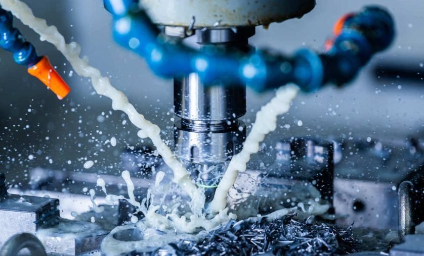
Parts go through the relevant processes: laser cutting, CNC press brake bending, MIG or TIG welding, CNC machining, and assembly, depending on what the design requires. All of these capabilities sit under one roof.
Subsequently, parts move through finishing. Ashland offers powder coating, hot-dip galvanising, electro-plating, and anodising, all selected to match the application and environment the part will operate in.
Throughout production, Ashland’s ISO 9001 certified Quality Management System runs in the background. Every process follows documented procedures. Every batch meets the agreed specification. And every delivery ships with the quality documentation the customer needs.
What Makes Ashland Engineering’s Design Process Different
Many fabricators will manufacture to your drawings. Fewer will engage with you at the engineering design stage and help you get those drawings right in the first place.
Ashland Engineering does both. Their in-house engineering design capability means they can take a concept, a sketch, or an idea and turn it into a production-ready digital model. Their manufacturing capability means that model goes straight into production without leaving the building.
This end-to-end approach, from engineering design through to finished part, is why customers across the UK trust Ashland with projects ranging from one-off prototypes to repeat batch production for OEM supply.
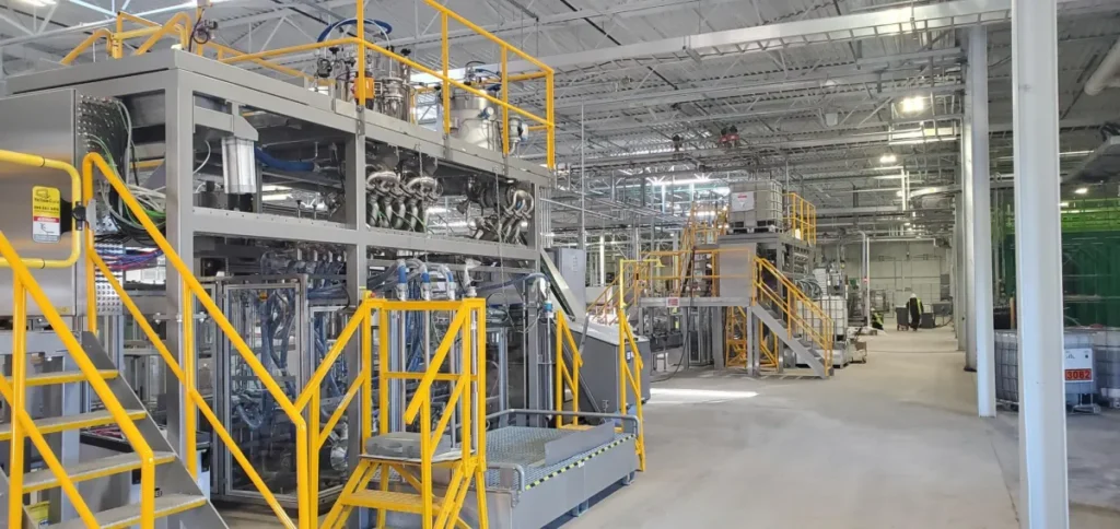
Real customer feedback confirms this. One client described how Ashland’s team interpreted their concept for a bespoke wash system for a motorsport powertrain customer, finalised the engineering design in CAD, handled complex sheet metal fabrication and extensive TIG welding, and delivered a finished product that surpassed all expectations.
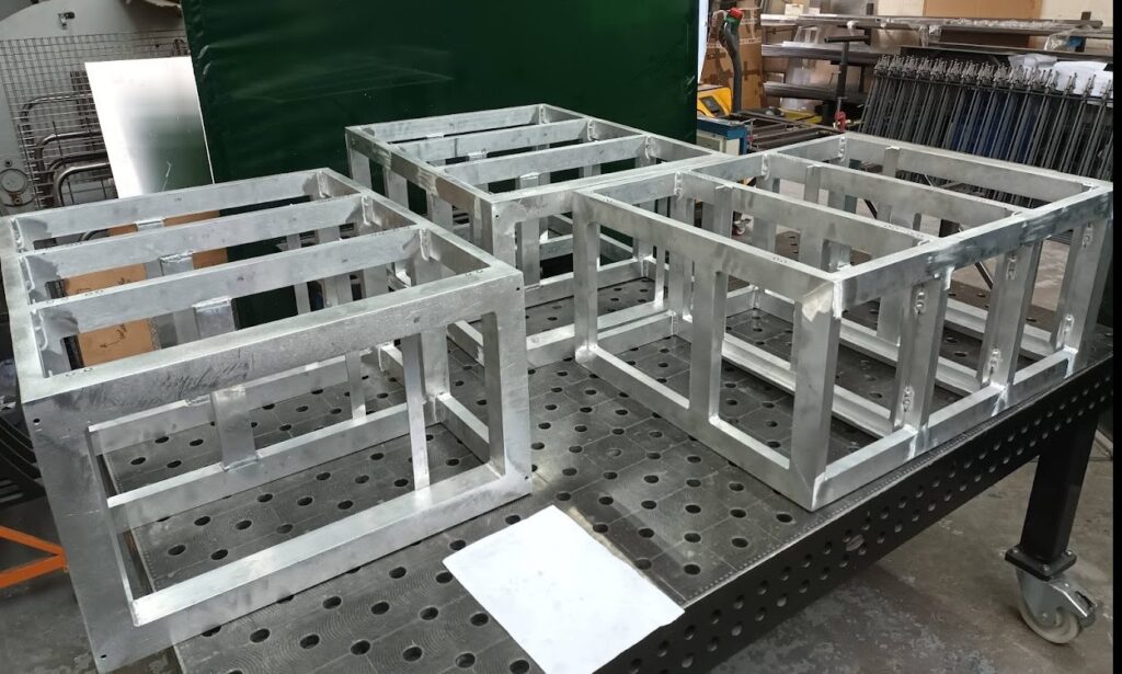
Another long-term manufacturing customer highlighted years of collaborative design-and-make work, with Ashland designing and manufacturing bespoke assembly fixtures, bench extensions, and special-purpose frames for their production line, all delivered on time and to the required standard.
Ready to Start Your Engineering Design Project?
Whether you have a finished drawing or just an idea in your head, Ashland Engineering can help you take it from concept to finished part.
Based in Milton Keynes and serving customers across the UK, get in touch today at sales@ashlandengineering.co.uk or call 01908 382 599 to discuss your engineering design project.